NOTE: This User Guide is general in coverage of the vehicle components and systems. Some of the exact equipment or functions may have been changed due to continuous product improvement. Your vehicle might differ slightly from the information included herein. Descriptions, images, and specifications were correct at the time of printing, but VanCraft LLC reserves the right to make changes, without notice, and without obligation to install the same products previously manufactured. In addition to this User Guide, your Campervan came with the manufacturer’s user manuals for various appliances and systems in your Campervan. Many of these systems are covered in this User Guide, but some information may only be found in the manufacturer’s manuals. Please keep these documents handy should you have questions.
Your VanCraft Campervan was built on a Mercedes-Benz® Sprinter chassis. You will find references throughout this User Guide to the Sprinter chassis and Sprinter operating instructions provided with the vehicle. Please refer to the Sprinter operating instructions for information regarding the operation, safety, and maintenance of the original vehicle chassis.
SAFETY AND PRECAUTIONS
SAFETY MESSAGES USED IN THIS USER GUIDE
This User Guide alerts you to common safety or vehicle hazards using the following labels:
|
⚠️ WARNING ⚠️ |
|
Indicates a hazardous situation which, if not avoided, could result in death or serious personal injury. |
Pre-Delivery Inspection: VanCraft Campervans takes pride in providing a high quality campervan product. Our team inspects every Campervan closely before delivery. Our team is responsible for completing a comprehensive pre-delivery inspection and correcting any issues with the chassis or Campervan components prior to delivery. Before driving, familiarize yourself with all local and state laws as different areas may have laws that apply to your Campervan.
VanCraft will be glad to provide any additional information you need, as well as answer any questions you might have about operating the equipment in your campervan. When it comes to service, remember that VanCraft knows your vehicle best and is interested in your satisfaction. VanCraft will provide quality maintenance and any other assistance that you may require during your ownership of this vehicle.
DRIVING AND PASSENGER SAFETY
- All seats should be locked in the travel position while the vehicle is moving. Passengers should only use seats with seatbelts while the vehicle is moving.
- Child restraints should be installed properly according to the manufacturer’s instructions.
- Never let passengers stand or kneel on seats while the vehicle is moving.
- All tables should be stowed when the vehicle is moving.
- Verify doors and drawers are shut and latched, where applicable, when the vehicle is moving.
- Passengers should never use the beds while the vehicle is moving.
|
⚠️ WARNING ⚠️ |
|
Operating, servicing and maintaining this vehicle can expose you to chemicals including engine exhaust, carbon monoxide, phthalates, and lead, which are known to the State of California to cause cancer and birth defects or other reproductive harm. To minimize exposure, avoid breathing exhaust, do not idle the engine except as necessary, service your vehicle in a well-ventilated area and wear gloves or wash your hands frequently when servicing your vehicle. For more information go to www.P65Warnings.ca.gov/passenger-vehicle. |
|
⚠️ WARNING ⚠️ |
|
This motorhome has been designed, manufactured and tested with concern for the protection of its occupants. We recommend you perform the following inspections for your safety and the safety of your passengers before starting your vehicle. WHEELS – Inspect for damage and check lug nuts for tightness. TIRES – Inspect for wear and damage and check for recommended air pressure. LIGHTING – Test for proper operation of all interior and exterior lights including dash lights, headlights, and turn signals. EXITS –Test both locks on the main entrance door for ease of operation and instruct passengers how to use both means of exit. SEAT BELTS – Direct passengers to designated seats, be certain swivel seats are locked into position, and require use of a seat belt. See operator’s manual for occupancy and weight restrictions. APPLIANCES – Turn off and latch or lock doors where provided. LOOSE PARCELS – Store securely. |
- Do not attempt to adjust the driver’s seat while the vehicle is moving.
- Do not adjust tilt steering in a moving vehicle.
- Do not operate the cruise control on icy or extremely wet roads, winding roads, in heavy traffic, or in any other traffic situation where a constant speed cannot be maintained.
- Use care when accelerating or decelerating on a slippery surface. Abrupt speed changes can cause skidding and loss of control.
- Driving through water deep enough to wet the brakes may affect stopping distance or cause the vehicle to pull to one side. Check brake operation in a safe area to be sure they have not been affected. Never operate any vehicle if a difference in braking efficiency is noticeable.
- Adverse weather conditions and extremes in terrain may affect handling and/or performance of your vehicle. Refer to your chassis manual for complete and related information on driving your vehicle.
- Doors - Verify all interior and exterior doors are shut and/or stowed and latches are in place where provided.
CARBON MONOXIDE WARNING
|
⚠️ WARNING ⚠️ |
|
Avoid inhaling exhaust gasses, as they contain carbon monoxide, which is a colorless, odorless, and poisonous gas. Death or serious injury can result. |
Combustion engines emit carbon monoxide (CO), which can be harmful or potentially deadly.
Keep CO out of the cabin by maintaining the vehicle exhaust and the ventilation systems. Have the exhaust system inspected from time to time by a qualified RV service center:
- When the vehicle is serviced.
- If the sound of the vehicle exhaust system changes.
- When damage occurs to the exhaust, underbody, or rear of the vehicle.
To allow for proper operation of the vehicle’s ventilation system, keep the front grill clear of snow, leaves, or other obstructions.
Refrain from idling your van for extended periods of time. Prolonged engine idle may clog your vans DEF filter causing exhaust leaks, and drivability issues.
|
⚠️ WARNING ⚠️ |
|
Do not occupy a parked vehicle with the engine running for an extended period. Do not run the engine in confined areas, such as a garage, except to move the vehicle in or out of the area. |
FIRE SAFETY
Your campervan is equipped with an alarm that will sound if it detects smoke or carbon monoxide in your vehicle. This system should be tested after the vehicle has been in storage, before each trip, and at least once per week during use by pressing the Test/Reset button.
|
⚠️ WARNING ⚠️ |
|
Test combination smoke / carbon monoxide alarm operation after the vehicle has been in storage, before each trip, and at least once per week during use. Failure to do so can result in death or serious injury. |
|
California Proposition 65 Warning: Battery posts, terminals, and related accessories contain lead and lead compounds, chemicals known to the state of California to cause cancer and reproductive harm. Wash hands after handling. |
FIRE EXTINGUISHER
Location of Fire Extinguisher:
- The fire extinguisher is located behind the passenger seat at the base for easy access in case of emergency.
- Ensure the fire extinguisher is easily accessible and not obstructed by other items.
Fire Extinguisher Type:
- The campervan is equipped with a 1-A: 10B:C fire extinguisher, suitable for most common fires such as paper, electrical, and cooking oils.
Inspection and Maintenance:
- Check the fire extinguisher regularly to ensure it is fully charged and in proper working condition.
- Ensure the pressure gauge shows in the green zone.
- Check for any visible damage or corrosion. Replace or service the extinguisher if necessary.
How to Use:
- Remember the acronym PASS:
- Pull the pin to break the tamper seal.
- Aim the nozzle at the base of the fire.
- Squeeze the handle to release the agent.
- Sweep the nozzle from side to side to cover the fire.
Emergency Procedure:
- If a fire occurs, first ensure your safety by evacuating the campervan if necessary.
- Use the fire extinguisher only if the fire is small and manageable. If in doubt, evacuate and call emergency services immediately.
Expiration and Replacement:
- Fire extinguishers should be replaced or recharged after the expiration date.
- Follow the manufacturer's guidelines for expiration and service dates.
Training:
- It’s important to familiarize yourself with the use of the fire extinguisher. We recommend practicing fire safety and extinguisher use before taking the campervan on the road.
EMERGENCY EXITS
Main Sliding Door: The main sliding door is the primary exit point.
Driver and Passenger Door: In the event that the side door is inaccessible, the front driver and passenger doors can be used as secondary emergency exits.
Rear Garage Doors: Do Not Use the rear doors as a means of emergency exit because the inside handle can be difficult to release from inside the van.
PINCH HAZARDS
Any time items open and close, like a door or cabinet, or move, like a rotating or folding seat, there is a potential pinch point. Avoid any moving areas of a mechanism to prevent injury.
FORMALDEHYDE INFORMATION
Like in every home and building, some materials in this Campervan may emit formaldehyde. Eye, nose, and throat irritation, headache, nausea, and asthma-like symptoms, including shortness of breath have been reported as a result of formaldehyde exposure. Reaction to formaldehyde exposure may vary among individuals and research is continuing on the possible long-term effects of exposure to formaldehyde. Inadequate ventilation may allow formaldehyde and other contaminants to accumulate in indoor air. Ventilate your RV before and during each use using the windows, exhaust fan or air conditioning system. If you have any questions regarding formaldehyde, consult your doctor.
MOLD
Mold is a natural part of our environment. It plays an important role in helping break down dead leaves and organic matter into fertile soil. The very nature of your RV being outside will bring it into contact with mold, but indoor mold growth should be avoided.
To reduce mold growth, reduce the things in your RV that could allow mold to grow. Mold only needs small amounts of moisture and nutrients from food spills or grease, it can survive on as little as a fine layer of dirt or dust.
Keep the inside of the vehicle as clean and dry as possible. Moisture plays a large part in mold growth. Don’t allow condensation to build up inside the vehicle and keep the interior humidity levels low. Proper ventilation helps and using the air conditioner and/or the auxiliary diesel heater can remove excess moisture from the air.
Avoid and repair leaks immediately as they are a major contributing factor to mold growth. If mold develops, clean the area with soapy water followed by a bleach solution. If the items cannot be treated, they should be removed and replaced.
MOLD AND WARRANTY CLAIMS
If VanCraft determines that mold in your campervan was caused by a manufacturing defect reported to VanCraft within the warranty period, VanCraft will clean the affected area(s) and /or replace items it deems necessary. This is the only circumstance in which VanCraft will cover mold under its limited warranty.
VanCraft, LLC will not assume responsibility for mold deemed to be a result of a user’s lack of timely and appropriate action to mitigate circumstances should a problem occur.
CONDENSATION
When it is humid in the van, condensation can develop inside the windows which can lead to damage if not properly addressed. It is best to keep moisture low with proper ventilation, but under certain circumstances ice can form if excessive condensation gets trapped between a window shade and the glass. If the ice or excessive sweating is not addressed and dried properly, it can melt and drip into the dashboard, electronics, upholstery or other areas that water may damage. Do not allow water to enter sensitive areas by carefully removing ice and drying the moisture to prevent damage.
TIP: When using window shades, position the shades as close to the glass as possible to prevent moisture build up. VanCraft, LLC does not assume responsibility for damage caused by water dripping into the dashboard, upholstery or other areas related to condensation or ice melting into those areas.
ELECTRICAL CAUTIONS
|
⚠️ WARNING ⚠️ |
|
Careless handling of electrical components can be fatal. Never touch or use electrical components or appliances while feet are bare, while hands are wet, while standing in water, or on wet ground. |
Avoid overloading electrical circuits and only replace fuses or circuit breakers with those of the same size and amperage rating. Never use a higher rated fuse or breaker. Use caution when handling or working near energy storage systems and electrical components. Always remove any jewelry and wear protective clothing and eye covering and avoid creating sparks.
GENERAL VEHICLE INFORMATION
LOADING THE RV
Before driving, always secure loose items which can become dangerous projectiles in sudden stops, quick maneuvers, and accidents. Distribute weight evenly to help vehicle handling.
Never exceed the GVWR (Gross Vehicle Weight Rating) or the GAWR (Gross Axle Weight Rating). GVWR is the total allowable weight of the vehicle, including passengers, cargo (including water), and possible tongue weight of a towed trailer.
The GAWR is the weight the axle is rated for. The combined measured weight at the front wheels plus the measured rear wheel weight should never exceed GVWR. Additionally, never exceed the individual tire weight ratings. Never exceed the GCWR (Gross Combination Weight Rating), the maximum total weight of the vehicle and anything towed.
WEIGHING THE RV
Weigh your fully loaded van to determine the proper load distribution of cargo in your vehicle. Weigh fully loaded, including fuel, fresh water, food, bedding, passengers, gear and other items you will carry.
FINDING A SCALE
Commercial truck stops usually have scales, but there are other commercial scales around that may charge a small fee.
WEIGHING PROCEDURE
Measure the front axle weight, rear axle weight, total vehicle weight. To get a front axle weight, drive only the front wheels onto the scale. To get a total vehicle weight, drive all wheels onto the scale. To get a rear axle weight, drive the rear wheels only onto the scale. Compare these measurements to the GVWR, and the GAWR for the front and rear axles, found on the Vehicle Certification label inside the driver door area.
TOWING WITH YOUR VAN
The Sprinter is rated to tow a maximum load of 5,000 lbs. Towing capacity may be less than the hitch rating based on the weight of your loaded vehicle. When towing, do not exceed the GVWR, the rear axle GAWR, or the chassis GCWR by the combined loaded weight of the VanCraft Campervan and the towed item. Towing will affect vehicle handling, durability, and fuel economy. Exceeding any of the listed Gross Weight Ratings will result in unacceptable overall vehicle performance and, potentially, danger.
HITCH ASSEMBLY
If a towing brake system is required, we recommend use of a modulated braking device versus a surge-style system. The actual tongue weight should never exceed the stated hitch vertical load. This is typically defined as the tongue weight of a towed vehicle hitch, boat trailer tongue weight, or a receiver-mounted carrier rack.
ROADSIDE EMERGENCY
Due to the weight and size of the vehicle, we recommend you seek professional road service to help in the event of a roadside emergency such as a flat tire. If the situation requires you to change a flat tire yourself, be very careful and read all the information in your Sprinter Operating Instructions regarding the changing of a tire. Check your tires for proper inflation before each trip, and at least once a month, using an accurate tire gauge.
IF YOU GET A FLAT TIRE
Do not panic. Grip the steering wheel firmly and steer the vehicle as straight as possible. You may need to counter-steer to compensate for pull created by the failed tire. Do not stomp/slam on the brakes. Do not jerk your foot off the accelerator. Just ease back on the accelerator slowly and gently to continue the momentum. The deflated tire will slow the vehicle. If you must change lanes to get to a safe stopping place, use your signals to warn other motorists and change lanes smoothly after you are certain the lane is clear. Let the vehicle coast to a stop, gently steering to a safe stopping place, then activate the hazard flashers and exit the vehicle carefully. Set out flares or other warning devices.
RECOVERY TOWING
Due to modifications of the RV from its original chassis specifications, notify the towing service of the height and weight of the RV (Height is 9 '+) as it may change how they recover the vehicle. This information is found on the Vehicle Certification Label. Refer to the Sprinter Operating Instructions on towing the Sprinter. VanCraft, LLC does not assume responsibility for damage incurred while towing this vehicle.
ENGINE OVERHEATING
If you see or hear steam escaping from the engine compartment or have reason to suspect an engine overheating condition, pull the vehicle over, stop the engine, get passengers out of the vehicle and consult the Sprinter Operating Instructions.
JUMP STARTING
If you wish to try jump-starting the engine, see the Sprinter Operating Instructions.
DRIVING YOUR CAMPERVAN
See your Sprinter Operating Instructions for information on items like driving controls, instrumentation, cruise control, climate controls, gauges, wipers, lights, safety belts, and other chassis related features.
FRONT SEATS
The front seats of your van are adjustable in various ways. The passenger seat swivels to face the rear of the vehicle. In some models the driver seat swivels as well. See your Sprinter Operating Instructions for more information on front seat adjustments.
NOTE: Damage to interior door panels may result if seats are swiveled toward the doors. Do not turn the passenger seat clockwise, adjust the seat all the way toward the front of the van before spinning.
NOTE: When the vehicle is in motion, the driver and passenger seat must be locked in the forward position.
SEAT BELTS
All seating positions have seat belts which should be used anytime the vehicle is in motion.
|
⚠️ WARNING ⚠️ |
|
Never sit anywhere in the van that does not have a seatbelt while the vehicle is in motion. |
NOTE: After any serious accident, all seat belts in use during the accident must be inspected and replaced if necessary.
CHILD RESTRAINTS
When properly used, child restraint systems reduce the risk of injury in an accident or sudden maneuver. If installed or used incorrectly, child restraints can increase the risk of injury. Refer to your child restraint system’s instructions for installation instructions.
NOTE: Rear bench seating can be used with a child restraint system designed for use with lap-only style seat belts.
NOTE: The rear bench seating does not have a ratcheting style belt retractor.
FACTORY DASH CLIMATE CONTROLS
The Sprinter dash climate controls were designed to heat and cool the front cabin area only, not the entire cabin. See Sprinter Operating Instructions for details and instructions covering dash A/C, heat, and defrost functions. See the Cabin Climate Control System section of this User Guide for details regarding the VanCraft Campervan heating and cooling systems. Infotainment Systems and Driver Assist Features Consult the Sprinter Operating Instructions for information and operation instructions regarding your Sprinter infotainment, radio, navigation, Bluetooth, cameras, external sensors and the like.
VEHICLE MAINTENANCE
The VanCraft Waypoint is built on a Sprinter chassis and requires routine maintenance and service outlined in the Sprinter Operating Instructions.
FRONT AXLE ALIGNMENT AND TIRE BALANCING
Once the campervan is fully loaded, get the alignment checked and adjusted, if necessary. After that, the alignment should be periodically inspected to help prevent uneven tire wear. Excessive or abnormal tire wear may indicate worn or misaligned suspension, an unbalanced tire, or other problems. Alignment can also be affected by incidents such as hitting a curb, pothole, or railroad track.
NOTE: Have a service technician inspect your vehicle’s suspension and steering components periodically for misalignment or wear. Refer to the Sprinter Operating Instructions provided with your vehicle for further information.
TIRES
This vehicle came with tires different from the original Sprinter and has a modified tire label in the driver door area with information regarding proper tire pressures.
NOTE: Improper tire pressure can cause abnormal or premature wear, affect vehicle handling, and fuel economy. The wheel lug bolts needed to be checked and torqued periodically and any time the wheels were removed and reinstalled.
SPARE TIRE
Refer to the Sprinter factory manual for information on accessing the spare tire.
ELECTRICAL SYSTEM OVERVIEW
OFF-GRID POWER SYSTEM
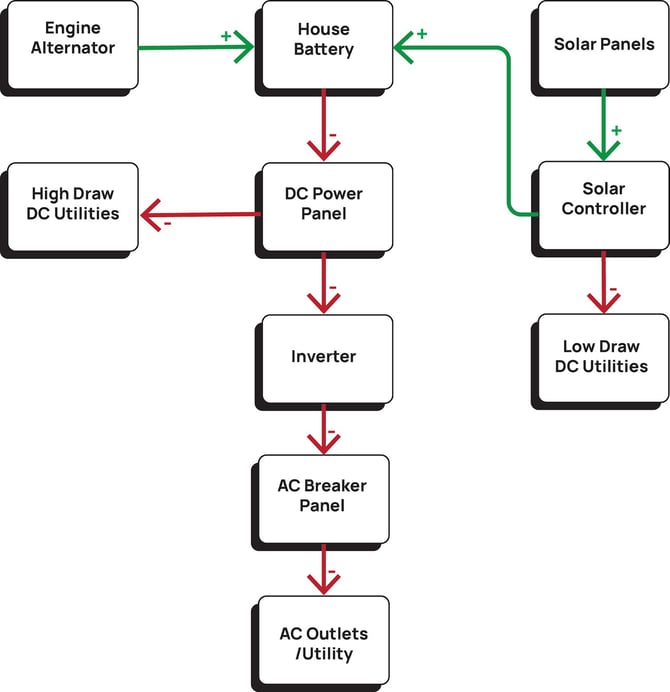
The heart of your Vancraft campervan is its off-grid power system. Centered around a lithium House Battery bank, your power system charges from several different sources. Electricity from the House Battery bank powers all of your devices, either directly or indirectly when converted to AC power via the included Inverter system.
|
House Battery |
The House battery bank is made up of multiple 200 amp/hr lithium ion batteries from Renogy power. Batteries are paired together to make up-to 600 amp/hrs. These batteries are “self-heating” meaning they discharge a small amount of electricity to keep themselves warm in cold climates, extending their cold weather performance. See “Power System Controls” on page “22” for information on battery monitoring and controls. See the linked manual from Renogy at the end of this manual for further information. |
|
Engine Alternator |
As you drive, the engine's alternator charges the house battery bank. This charge current is automatically controlled by a Victron Energy Smart Charge Relay located under the driver's seat. There is no need to worry about depleting your vans starter battery as the charge relay disconnects charge current when the starter battery begins to see decline in charge. Incoming charge to the House Battery from the engine alternator can be seen on the Renogy Core One power system screen, read more about this on page “21”. |
|
Solar Charging |
The Renogy roof mounted solar panels send raw power directly to the Solar Charge Controller. The Renogy Rover solar charge controller then sends optimized charging current to the house battery bank. Low draw DC Utility is also powered directly from solar power. For more information on the Renogy Rover including a list of Low Draw DC utilities, monitoring, and system settings, see the “Utility Bay Electrical” section on page ”25”. |
|
DC Power Panel |
The Power Panel is the analog control center for your vans off-grid power system. The panel serves as a battery compartment door, it houses breaker switches and fuses for all High Draw Utilities, and has a built-in plug for battery tending while the van is stored. You can read more about the DC Power Panel on page “23”. |
|
Inverter |
Much of your vans system and vehicle chassis operate utilizing a 12v/DC electrical system. Direct Current is convenient and efficient but does not work to power our favorite devices brought from home. The electricity in your home is generally based on a 120v/AC system. The “Inverter” converts the DC power output of your battery to 120v/AC power supply to outlets and AC based appliances installed in your van. More information about your Inverter and AC breaker panel can be found on page “28”. |
TECH STACK
Located on the right side of the closet, above the kitchen counter, the Tech Stack is your vans centralized command station. Control your vans power system, lights, Roof Auxiliary Power, HVAC and more. 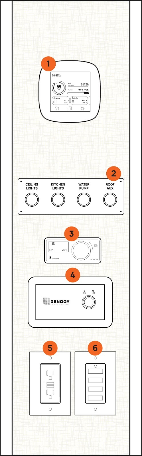
|
1 |
The Renogy Core One screen controls and monitors your vans DC electrical system. More information can be found on page “21”. |
|
2 |
Lights, water pump and Auxiliary Roof Power can be turned on and off. If the indicator light is on then the labeled device is powered. More on “Roof Aux” can be found on page “41”. |
|
3 |
The onboard Espar Diesel heating system is controlled by the “Easy Start Pro” by Eberspacher. For information on running your diesel heater see “Diesel Cabin Heater” on page “30”. |
|
4 |
The Renogy 3000W Inverter control switch. Turn the inverter on/off to supply power to 120V AC outlets and induction cook stove. More information about the inverter can be found on page “28”. |
|
5 |
120V AC GFCI power outlet. An LED indicator light illuminates when the Inverter is supplying power. This outlet provides a 15amp max current. |
|
6 |
DC 12V USB outlets. These four USB outlets provide power to charge your devices. Each outlet is rated for 2.5 amps or 30 watts. |
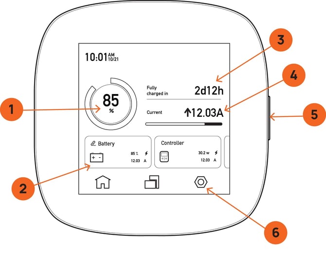
Renogy Core One
|
1 |
SOC or “State of charge” is shown in percentage. This is the simplest, fastest way to quickly see the state of your van battery. SOC works just like the percent charge for your phone or laptop. |
|
2 |
On the home screen (as shown) a list of connected devices is displayed in card format. You can scroll through all connected devices with the swipe of a finger. Each card shows some quick info for each device. You can see a complete list of each device or add a new one on the “Connected Devices” screen by clicking the icon on the bottom center of the screen (left of the system settings icon). |
|
3 |
“Time until charged” is displayed in days and hours. This calculation is based on a depleted battery divided by incoming charge in amp/hours and indicates how long that charge will take to top off your battery. It’s important to know that this calculator will change rapidly depending on the consistency of the incoming charge. |
|
4 |
Incoming or outgoing current is displayed in amps. An upward arrow (↑) next to the amperage figure shows a gain while a negative symbol (↓-) shows a loss. If the battery is topped off to or around 100% the batteries will no longer take a charge and will display 0.00 here. |
|
5 |
The sleep button will turn the screen off when pressed quickly. Long pressing this button will turn the Renogy Core One off. If you are experiencing issues with connectivity to your devices this is a good way to reset the bluetooth system. |
|
6 |
System Settings allows you to add or remove devices through the Bluetooth pairing process, check the vans level, as well as change system settings like time and date. |
Battery Information Monitoring
Take a deeper dive into battery information by pressing on the battery information card on the home screen (2). Here you can see SOC in various units of measure for the entire battery life as well as each battery individually. Battery banks of 400 amps should have two batteries connected, 600 amp banks should have three. You can add or remove batteries in the add device screen accessed via the system setting menu (6) or from the device list icon in the bottom center of the home screen.
Solar Controller Monitoring
Take a deeper dive into the Solar Controller monitoring capabilities of the Renogy Core One by selecting the Solar controller card on the home screen. On this screen you’ll get a breakdown of incoming charge isolated to the solar controller specifically. You’ll also see a radio button that switches Load Output on and off. More on the functions and control of “Load Output” can be found in the Utility Bay section on page “24”.
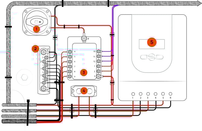
DC Power Panel
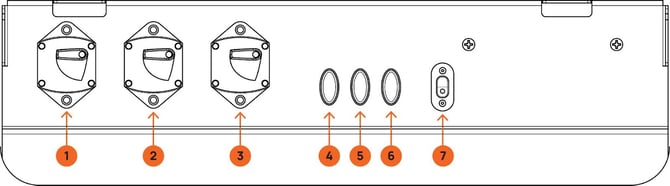
The Power Panel can be accessed by removing the false face of the bottom drawer in the kitchen base cabinet. The Power Panel helps provide organized and easy access to the main analog service points of the power system.
|
1 |
Solar Controller breaker switch: 40 amps. Turning this breaker off will disconnect the House Battery connection. It is important to note that with this breaker switch turned off, the Solar Controller may still be energized by the solar panel. The solar panel itself can be disconnected in the utility bay from the thermal breaker, read more on page “24”. |
|
2 |
Battery to battery charge relay breaker switch: 150 amps. Turning this breaker off will disconnect power to and from the House Battery and the Victron Smart Charge Relay under the driver seat. It is important to note that with this breaker switch turned off, the charge relay may still be energized from the starter battery fused connection. The starter battery fuse is located in the starter battery box, read more about accessing your vans start battery storage box in your Mercedes chassis manual. |
|
3 |
Inverter breaker: 200 amps. Turning this breaker off will disconnect the House Battery from the Inverter. |
|
4 |
Auxiliary roof power fuse slot. This fuse slot comes empty upon delivery unless optional roof equipment is included with the sale of the van. For more information about Auxiliary Roof Power see page “41”. |
|
5 |
Refrigerator Fuse: 15amps. This fuse protects the power circuit to the Dometic refrigerator. |
|
6 |
Battery tender power input fuse: 25 amps. This fuse slot protects the charge circuit from the SAE plug (7) on the diagram.
|
|
7 |
This charge input allows you to plug in a battery tender when your van is stored for extended time. Read more about storing your van on page “44”. |
Utility Bay Electrical
Located under the bed in the utility cabinet on the passenger side, the Utility Bay Electrical area houses the Renogy Solar Controller and all of its related components.
|
1 |
The Disconnect switch physically disconnects Load Output from the Renogy Rover charge controller (5). This is the surest, safest method to disconnect power to the fuse box (3) before servicing are working around any Low Draw DC utilities powered by the Solar Controller. |
|
2 |
The negative bus bar consolidates all negative connections for each circuit from Load Output. |
|
3 |
The fuse box houses all fuse connections for Low Draw DC circuits controlled by Load Output of the Renogy Rover Solar Controller (5). When a fuse is blown, a red indicator light will illuminate next to it. A fuse diagram is adhered to the side wall in this cabinet as well as included in the Circuit Protection section on page “25”. |
|
4 |
The thermal breaker protects the incoming Solar Panel circuit from overload. |
|
5 |
The Renogy Rover Solar Charge Controller controls solar battery charge and load output to Low Draw DC utilities. Load output is indicated as “on” when the indicator LED with a light bulb icon is illuminated on the top center of the Rover. Turn Load Output on and off with a firm press of the right arrow key while on the home screen, from the solar controller menu of the Renogy Core One or from your smart phone while using the Renogy DC app. Further information about the Renogy Rover and the Renogy smart phone app are linked in the Manual Links at the end of this document. |
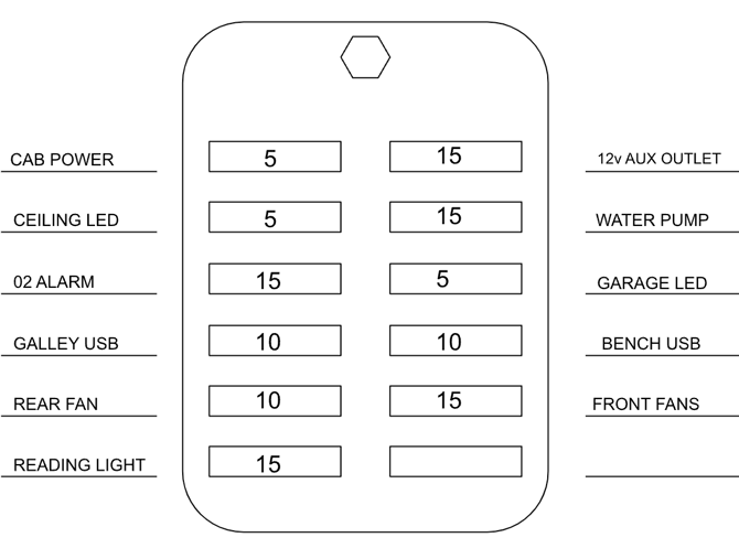
Circuit Protection
Fuse Boxes
Mercedes installs fuses in three major locations in the chassis. Refer to your Mercedes owners manual for detailed information about chassis fuse locations and accessibility.
VanCraft uses fuses throughout the electrical system, there are three major locations:
Utility bay Electrical for Solar controller load output is described on page ”24” diagram reference 3. The reference diagram below details the fuse layout and sizing for your vans solar controller Load Output.
**The layout of your fuse block may differ from this diagram with the addition of optional equipment. Refer to the diagram in your van Utility Electrical Box for the most accurate diagram.
The electrical Power Panel has a small group of fuses that are detailed in the “Power Panel” Section on page “23”.
A bank of fuses are also located under the driver's seat. Access these fuses from the driver door area by removing the access cover on the driver seat base. Fuses in this area are as follows:
|
Yellow Fog Bumper Pod Lights |
15 Amp |
|
White Fog Bumper Pod Lights |
15 Amp |
POWER OUTLETS
|
Location Waypoint |
Outlet Type |
|
Tech Stack |
1x 110v GFCI outlet |
|
Tech Stack |
4x USB Ports |
|
Rear Reading Lights |
2x USB Ports |
|
Bench Seat Area |
1x 110v GFCI outlet |
|
Chassis Driver Area |
See Mercedes-Benz Manual |
LIGHTING
Main Ceiling Lights: Turned on and off using the labeled push button located on the Tech Stack. Located along the roof of the van.
Garage Lights: Turned on and off using the labeled push button on the plumbing control panel, on the rear of the Utility bay. Located on the roof of the garage area.
Kitchen Area Lights: Turned on and off using the labeled push button located on the Tech Stack. Located on the underside of kitchen roof cabinets.
Reading Lights: Located on both sides of the main sleeping area in the rear of the van. These lamps are turned on and off with a tap of the touch sensitive switch on the face of the light fixture. A long hold/press of the touch sensitive switch dims the lights. On the bottom of the round main body of the light fixture is a single USB plug.
TROUBLESHOOTING STEPS FOR CHARGE SYSTEM ISSUES:
If you are experiencing unusually low battery levels, or your utilities stop working all together - work through these fixes in order.
 Check your battery is charged above 25%.
 Check that power is coming/going from the battery.
 - Check to see if “Load output” is turned on on the Solar Controller.
- Check to see breakers are “on” in the power panel.
- Check to see fuses are not blown.
- Check solar controller is set to 12v system.
- Check solar controller is set to lithium battery type.
120V AC Electrical System
Much of your vans system and vehicle chassis operate utilizing a 12V/DC electrical system. Direct Current is convenient and efficient but does not work to power our favorite devices brought from home. The electricity in your home is generally based on a 120V/AC system. The “Inverter” converts the DC power output of your battery to 120V/AC power supply to outlets and AC based appliances installed in your van.
|
⚠️ WARNING ⚠️ |
|
Electric Shock Hazard: Always ensure the inverter is installed and maintained according to the manufacturer’s instructions. Do not attempt to service the system yourself unless you are qualified to handle electrical systems. |
Inverter
The Renogy 3000W Inverter is mounted on the underside of the closest bottom shelf. It can be turned on/off using the Renogy power switch on the “Tech Stack”. Power output from the inverter is sent to the main breaker switch in the 120v/AC breaker panel behind the flip-up bench back. The inverter also has its own breaker that may be tripped if over-loaded. Power feed to the inverter is controlled by the 12v/DC breaker switch on the “Power Panel ”. If the Regnoy Power Inverter has an error, a red indicator light will illuminate on the face plate of the off/on switch. Error codes are found in the manufacturers manual, linked at the end of this manual.
|
⚠️ WARNING ⚠️ |
|
Do Not Overload the Inverter: Ensure that the total power draw from your appliances does not exceed the inverter’s rated output. Overloading can damage the system and connected devices |
120V AC Breakers
The AC breaker panel is located behind the front facing bench backrest. Lift the bench backrest up to the locked sleeping position to access the breaker panel access door on the passenger side of the bench back.
The labeled Breaker Panel has a main breaker for incoming power from the Inverter for power distribution the the remaining circuit breakers for each branch circuit.
Trouble shooting the 120V AC System
If power outlets or AC appliances are not functioning; check the following:
 The inverter is turned “ON”. A green light on the control switch mounting plate illuminates. The front screen on the inverter charger (located under the rear forward facing bench seat) is on and showing status
- The 12V/DC breaker for the Inverter is turned “ON”. This breaker is located on the “Power Panel” Described on page “23”.
- All breakers in the 120V/AC breaker panel/power distribution panel are not tripped and are in the “ON” position.
- There are no error codes indicated.
- The Breaker on the Inverter itself is not tripped.
CABIN CLIMATE CONTROL
OPTIONAL AIR CONDITIONING SYSTEM
Before using the air conditioner, first familiarize yourself with its included instruction manual.
Your air conditioner is designed for off-grid style 12V DC power systems. It accomplishes this with its included “ECCO” run mode. “ECCO” mode cools your cabin at a max of an 18 amp draw. “Auto” and “Boost” modes use a considerable amount of electricity. Use these modes while driving for better cooling performance, the engine will supply more than enough power to charge the batteries while also running the air conditioning on its coldest settings. Save power by deploying the optional side awning to cast shade on the vans metal chassis. Optional window covers and rear bed insulated partition also greatly improve the air conditioner's power efficiency.
It should be noted that water will discharge off of the roof from the air conditioner in particularly humid climates.
USING THE EXHAUST FAN(s)
Vans without a roof air conditioner have an exhaust fan above the bed. Use this fan to prevent harmful gasses from building up inside the living quarters of the van, remove cooking odor from the van, and draw cool or hot air from the vans dashboard HVAC system to the rear of the van.
Only open the roof vent a quarter of the way while the van is in motion. Use the lock when closed.
DIESEL CABIN HEATER
Before using the cabin diesel heater, first read the included instruction manual. The heating system uses diesel from the Sprinter’s primary fuel tank to fire a small furnace for heating cabin air. The heater can be run with the van’s engine off and the inverter does not need to be on. Follow instructions in the heater manual (linked at the end of this manual) to turn the unit on and off and adjust cabin temperature.
NOTE: The diesel-fired furnace will not operate if the vehicle’s fuel tank level is under 1/8 tank.
NOTE: Do NOT turn off the 12V power system system if the furnace is on. This includes breakers, fuses, master power disconnect switch, and the solar controller itself. Turn the furnace switch to OFF on the heater controller only, then wait at least 10 minutes for the furnace to shut down properly.
TROUBLESHOOTING THE DIESEL HEATER
Troubleshooting steps can be found in the heaters instruction manual. If you are having a tough time starting the heater check that:
- The diesel tank is above 1/8 full.
- The battery system is sufficiently charged (25% minimum.
- You're operating the heater below 13,000 feet of elevation.
PLUMBING SYSTEMS
Plumbing System Controls 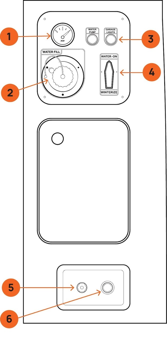
1. Water Level Gauge - The gauge shows the current level of water in your tank.
- Water Fill Port - The fill port allows for water to be filled via garden hose. Do not over fill the water tank.
- Garage Lights Button - Controls the lighting inside your van camper’s garage or storage area.
- Winterize Valve - This valve allows you to bypass the water pump and plumbing lines, preventing water from staying in the system and freezing, which can cause pipes to burst and other damage.
- Shrader Valve (PSI Port) - The valve enables you to connect an air compressor to your water system, forcing pressurized air through the lines to clear out any water that could freeze and damage the pipes.
- Water Access Port - The quick connect port provides a fast, tool-free method of connecting to a hose for relaying water to your outdoor shower or garden hose setup. Simply attach the compatible hose or water line to the port to access water for use in the outdoor shower.
FILLING THE WATER TANK
The water-fill port is located on the bottom left of the water control panel on the front face of the utility box (Ref. diagram above).
- Unscrew the cap on the fill-port.
- Using a standard garden hose (it is helpful to have a spray nozzle or shutoff valve attached), press the hose into the fill port opening and then begin the flow of water to fill the tank.
- As the tank fills, the tank fill gauge will read its level. If it is difficult to read the gauge, turn on the garage lights to illuminate the gauge.
- When the tank gauge reads full, turn off water flow from the gauge and screw the fill port cap back on. DO NOT OVER FILL THE TANK.
NOTE: It is important to clean up any spilled water immediately to avoid damage to the campervan’s cabinets, flooring, and other systems.
DRAINING THE FRESH WATER TANK
Drain the water tank using the tank drain valve located on the floor inside the plumbing utility access door below the plumbing control panel.
CLEANING THE TANK
- Fill the water tank half way and mix in ⅜ cup of household bleach into the tank before completely filling the tank with a total of 40 gallons of fresh water.
- Let the full tank sit for 4 to 8 hours.
- Drain the water tank using the tank drain valve located on the floor inside the plumbing utility access door below the plumbing control panel.
- Refill the water tank with fresh water and drain 3 times to flush the system.
Your van comes equipped with a complete water system. Your 40 gallon fresh water tank distributes water throughout your van with a water pump. Water is fed to your outside Spray Port and Kitchen Sink.
WATER PUMP
Your van's water pump can be turned on and off using one of two water pump switches. The water pump is “on” ONLY when the switch LED indicator ring light is illuminated. Switch one is located in the garage area on the Plumbing Control Panel on the front face of the utility cabinet. Switch two is located on the Tech Stack.
When the pump is on all water systems in the van are under pressure. Make sure all fixtures (faucet)are closed, and the outdoor spray port is disconnected before turning on the pump.
It is recommended to leave the water pump “off” when not in use.
OUTDOOR SPRAY PORT
Located on the bottom front face of the utility cabinet, your spray port gives quick access to pressurized water for outdoor use. An included quick connect hose can be used for clean up of gear and equipment before storing in the vans garage. Pair this hose with an optional door mounted hot water heater for a heated outdoor shower. When connecting the hose to the quick connect port, make sure the pump is not on.
USING THE OUTDOOR SHOWER
Your optional outdoor hot water shower provides on-demand hot water for showering and cleanup from the exterior of your van. This device is mounted to the rear door of the van, and is intended to only ever be used with the door open so that exhaust fumes can easily escape and not enter the living space of the van.
|
⚠️ WARNING ⚠️ |
|
This accessory hot water shower is designed for use in areas with direct airflow to the outdoors. NEVER use the hot water heater with the rear cargo door closed. NEVER leave the low pressure propane canister connected while the water heater is not in use or unattended. ALWAYS turn the hot water heater igniter switch to the “OFF” position when not in use. And only ever connect the water supply hose to the water heater when in use, NEVER LEAVE THE WATER SUPPLY HOSE CONNECTED WHEN THE SHOWER IS NOT IN USE. |
Please follow the steps below to operate your shower:
- Make sure the quick-connect spray port hose, shower head, and shower water flow valve are connected together firmly utilizing included rubber “O” rings at each connection.
- Connect propane to the low pressure regulator. DO NOT OVER TIGHTEN.
- Turn on the water heater flame igniter (located on the bottom of the water heater).
- Turn on the water pump. Water will then flow through the heater and out of the shower head. You will hear the igniter clicking.
- Adjust water temperature using the control knobs on the face of the heater.
- You can limit water flow or stop the flow of water completely using the flow adjustment on the shower head.
- When done, turn the water pump switch OFF.
- Open the shower head flow restrictor valve and release any residual water from the line by shaking the shower head below the tank level.
- Disconnect the propane bottle, disconnect and stow the quick-connect spray port, and turn the igniter switch off.
- Immediately wipe up any water that may have dripped inside the van.
NOTE: Always be sure to winterize your shower if you are camping or leaving your vehicle in freezing weather conditions.
|
Note: If an accessory is connected to the spray port and the water pump is turned on (from inside the van or from the utility cabinet) water will come out of the port. It is best practice to leave the spray port disconnected when not in use to prevent water accidentally spraying inside the van when the pump is turned on. |
KITCHEN SINK
The sink is pressurized by the water pump in the rear of the van. Press the water pump switch on the Tech Stack. The pump is on and the sink is ready to use when the switch is illuminated.
NOTE: Never leave the water pump on when not in use or when unattended. Always confirm the spray down port hose connection in the garage is DISCONNECTED before turning the pump on from inside the van.
KITCHEN SINK DRAIN
Avoid pouring chemicals, food scraps, or other harmful items down your sink drain.
NOTE: Always use the included sink strainer to protect the drain from items that may cause clogs.
WINTERIZING YOUR WATER SYSTEM
Any time there is a chance of your van becoming exposed to below freezing temperatures, it is vital that you winterize your plumbing to avoid breakage. While this process can be an all-day project in most RVs, our plumbing system is designed for rapid transition in and out of Winterization Mode . Follow these steps in order to prepare your vans plumbing for freezing temps.
- Drain your fresh water tank. Open the plumbing access door located on the rear face of the utility cabinet (below the water control panel). Inside you’ll see a series of hoses and your water tank. Reach inside the cabinet and turn the drain valve (located on the floor, inside the utility cabinet). Leave the drain open.
- Activate Winterize valve. Turn your winterize valve so that it points to “Winterize”. The winterize valve is located on the plumbing control panel on the rear face of the utility cabinet, under the bed.
- Setup Outdoor Shower. Make sure the water pump is off. If your van is equipped with an out-door hot water heater, connect your spray down port hose to the water heater and make sure the shower head is turned off so that no water can come out.
- Clear your lines. Make sure the sink faucet and spray down port are in the off position. Using a compressor with a minimum output of 45 PSI, equipped with a standard tire fill air chuck, connect the air chuck to the schrader valve on the bottom plumbing plate (located on the bottom face of the utility cabinet to the left of the outdoor spray down port) and apply compressed air to your system.
- Open the sink valve until water stops flowing, then close the valve.
- Open the outdoor shower head and turn the water flow adjustment (blue knob) to max. Turn off the shower head when water stops flowing.
- Remove sink aerator. Grab the tip of the faucet and remove the faucet aerator by turning counter clockwise. Store the aerator somewhere safe and re-install when un-winterizing your system.
At this point there should be no water in your system. In extreme and extended cold, it is recommended to put RV antifreeze in your plumping. It is also possible to fill the entire system with antifreeze for added protection by connecting a hose to the schrader valve and inserting the hose into a bottle of antifreeze. Run the water pump and open all taps until antifreeze flows at each orifice. Flush the system with clean water to un-winterize.
|
⚠️ WARNING ⚠️ |
|
NEVER use automotive antifreeze/ coolant in your RV water system. Automotive coolant/antifreeze contains ethylene glycol which, if ingested, can cause blindness and can be fatal. |
|
⚠️ WARNING ⚠️ |
|
Standing water left unattended in the van can cause damage to cabinets, floor, electronics and other components found in your campervan. Always take immediate action to clean up water spills and fix leaks in plumbing systems. If a leak cannot be fixed, drain all holding tanks until your van can be brought to a qualified service station for repair. Lastly, failure to winterize plumbing systems before the onset of below freezing temperatures can result in water leaks and subsequent water damage. |
APPLIANCES
REFRIGERATOR
The Dometic refrigerator is located in the kitchen base cabinet. The control panel is INSIDE on the left wall of the unit. The complete Dometic Manual is located in the helpful links section at the end of this document.
REMOVING THE REFRIGERATOR
In order to maintain, repair or send it in the refrigerator for warranty, the refrigerator may need to be removed.
- Remove white caps from inside the unit.
- Unscrew mounting system.
- Gently slide the unit out of the cutout location.
- Unplug from back of the unit.
- To re-install, follow instructions in reverse.
INDUCTION STOVETOP
The VanCraft Waypoint is equipped with a portable 1800W single burner induction cooktop that operates on 110V AC electricity. To use the cooktop, ensure that the power inverter is activated.
- Power Consumption: The induction cooktop consumes significant power quickly. Always monitor your battery usage closely to avoid power drain and potential malfunctions.
- Induction-Compatible Cookware: Only use cookware that is compatible with induction heating (minimum 4” diameter, magnetic). Non-compatible cookware may cause overheating and lead to safety hazards.
- Never Leave Unattended: Always monitor the cooktop while in use. Unattended cooking can lead to overheating or fire.
- Proper Ventilation: Ensure adequate ventilation around the cooktop. Overheating due to restricted airflow can result in damage or fire.
- Follow Manufacturer Instructions: Refer to the manufacturer’s user guide for detailed instructions and safety precautions related to the induction cooktop.
|
⚠️ WARNING ⚠️ |
|
Failure to follow safety guidelines in the units manual may result in fire, property damage, or injury. Always prioritize safety when using the induction cooktop. |
SEATING AND SLEEPING SYSTEMS
REAR BENCH
The rear bench-seat has room to seat (2) passengers. There are type-1, lap-belt style seat belts installed for each passenger. When the van is in motion all passengers MUST wear seat belts.
The cushioned horizontal bench-back folds up to extend the sleeping area of the bed. The bench back must be in the down position when passengers are riding in the back seats. Be conscious and attentive to make sure bedding is not pinched in the latch when engaging the bench-back to prevent damage to both the bench-back hardware and your bedding. Make sure both latches are engaged, by pushing down on the bench-back, before climbing up into bed.
|
⚠️ WARNING ⚠️ |
|
Do not try to collapse the bench back from on top of the bed. First climb out the bed and stand on the ground while lowering the bench back. Release the latches by pushing upward on the latch triggers. |
MAIN SLEEPING AREA
The elevated bed above the garage is designed to utilize the extension provided by the bench back when in the upright position. The recommended sleeping position is to place your head towards the rear of the vehicle and your heels resting on the bench-back extension.
BENCH SLEEPING
There is enough room for a child under 4’ tall to sleep horizontally on the rear bench seat.
Never sleep with your head under the bench-back when it is in the upright position.
- Before allowing passengers to sleep on the bench, ensure that the bench-back is securely locked in place. Test the security of the bench-back to confirm it cannot fall and cause injury.
Failure to follow these guidelines may result in injury or harm. Always prioritize safety when using the bench seat for sleeping.
EXTERIOR ACCESSORIES
ROOF RACK
The roof rack on your Vancraft Campervan is designed to provide additional storage space for gear, luggage, or recreational equipment, making your van-life adventures more efficient and organized. The inner racking is modular and can be spaced out to fit your needs by simply unscrewing the fittings and moving them to the desired locations. When loading items onto the roof rack, distribute the load evenly across the platform to ensure proper balance and stability while driving. Avoid concentrating too much weight at a single point.
|
⚠️ WARNING ⚠️ |
|
Do not exceed the 250 lbs (113 kg) weight capacity while the van is in motion. When transporting items on the roof rack, be aware that sudden or abrupt stops (such as emergency braking or quick halts) can cause your load to shift forward. |
ROOF AUXILIARY POWER
The auxiliary power system is connected directly to your campervan’s electrical system, allowing you to draw power from your house battery to power roof-mounted devices. There is a control switch to turn devices on and off inside the cabin on the Tech Stack. The connection on top of the van is an SAE 12V Plug. The fuse location for your auxiliary power is located on the DC Power Panel. It is important to know that your van ships without a fuse installed in the Auxiliary Roof Power fuse slot. Until a fuse is installed, power will not be available at the roof plug.
|
⚠️ WARNING ⚠️ |
|
Roof Auxiliary power is rated for 20 amp max DC load. Always read the included instructions with any device connected to the roof auxiliary plug to determine the appropriate fuse size to use in the Auxiliary Roof Power fuse slot. NEVER INSTALL A FUSE RATED LARGER THAN 20AMPS. |
FRONT BUMPER LIGHT PODS
Your campervan’s two-stage LED light pod system is integrated into the front bumper and is turned on via two red switches (to the right of the steering column). If the switches are illuminated red, the lights are turned on.
The white lights are intended for low light conditions, while the yellow lights are designed to cut through fog and snow. Like all electrical systems in your van, prolonged use could result in a dead battery.
AWNING
To best learn to operate your awning, refer to the included Fiamma manual. A how to video can be viewed here:
|
https://m.youtube.com/watch?v=2XjqKaUwtmM&list=UUAPH__3D5UtifJrJmDM8jPA&t=104s&pp=2AFokAIB |
|

The awning crank rod is stored under the bed in the garage area. The awning pitch adjustment screws have been adjusted to avoid the awning from hitting the top of the slider door when in the open position.
|
⚠️ WARNING ⚠️ |
|
Never Leave Awning Unattended: Always retract the awning when the camper van is in motion or when you are not present. Strong winds or sudden weather changes can cause the awning to become damaged or pose a safety hazard. Wind and Weather Conditions: Do not deploy the awning in high winds, storms, or other adverse weather conditions. Winds exceeding 15-20 mph can cause significant damage to the awning and pose a risk of injury. |
LADDER
Your Waypoint may be supplied with a ladder mounted on the rear driver’s side door. The ladder on your van is provided for limited access to the roof. Walking or working on the roof should be left up to qualified service personnel using proper safety equipment in a safe environment. You should only walk or work on the roof if you are qualified and have created a safe environment. DO NOT CLIMB ON THE LADDER WITH THE DOOR OPEN. Standing on the ladder with the door open will damage the door and hardware.
The ladder is rated for 275 lbs. Keep the rungs of the ladder clean and dry while in use. Never use the ladder when it is raining, snowing or icy. The rungs can become slippery. Do not step onto the rungs if the rungs are wet, or if your shoes are wet or carry mud or debris that could result in a loss of footing.
|
⚠️ WARNING ⚠️ |
|
STAY OFF ROOF. The surface may be slippery. Falling could result in death or serious injury. |
CAMPERVAN REGULAR MAINTENANCE
BUTCHER BLOCK COUNTERTOPS
VanCraft campervans come standard with solid oak butcher block countertops. These beautiful countertops are chosen for their elegance, durable makeup, and ease of maintenance. They are treated before installation with a 3-day soak in our favorite butcher block oil to seal them from water and stain intrusion.
Over time, your countertops will encounter stains and normal wear-and-tear. Spot treating and refinishing the butcher block is a regular part of campervan ownership. Additionally, your countertops will need regular re-applications of a good butcher block oil to keep them sealed and protected.
We recommend applying a nice sealant layer of oil every 4-6 weeks, when used regularly. You can find butcher block oil at your local hardware store or at many online retailers. Simply apply with a cloth and let soak for 2-3 hours before wiping away with a clean cloth. For more intensive spot treatment and refinishing, sand the oil into the grain of the wood using 120-200 grit sandpaper.
ROOF SEALANT
Your van’s roof accessories are sealed with a coating of “RV Lap Sealant” as an extra layer of protection from water intrusion, where fasteners penetrate the roof structure. Like all RV’s this lap sealant should be inspected and re-coated every 3 years. This can take place at any RV service center or can be done easily yourself. We recommend “Dicor 501LSW-1 Self-Leveling Lap Sealant” for your maintenance needs.
LATCH ADJUSTMENT
Your van's cabinet drawer and door latches may fall out of adjustment with time. Loading drawers with heavy cargo, off road driving, or a shift in climate can add to the misalignment of your latches. It is important to keep your latches adjusted properly so that your drawers, doors, and cargo stay put.
All latches have slotted screw holes so they can be aligned when necessary. Use a phillips screwdriver to gently loosen the latch and re-align before tightening.
STORING YOUR VAN
If you’re planning to store your van for an extended period of time, follow these steps to ensure your van is prepared for storage.
- Follow Mercedes Instructions for storing your van (see extended parking).
- Unplug all electrical appliances
- Winterize your plumbing: there must be no water in your van (Ref. winterization instructions)
- Disconnect utility from your solar controller on Utility Bay Electrical Diagram
- Turn off all breaker switches
- (Optional) Connect a battery tender in slot on DC Power Panel. This will ensure a healthy battery percentage during the storage process.